Jamie
JamieIntroduction
Smartphone repair used to be simple stuff; you replaced screens and changed out batteries, but now, it’s gotten a lot more complicated. Many problems with phones ending up completely dead come from the logic board. This is a small but very densely packed circuit board that controls a broad range of things in the phone, from power management to signal processing.
It’s more or less an art to be able to repair these types of boards; the art is a combination of electronics knowledge, a steady hand, and using proper tools. Technicians wanting to take a step from the basics of phones to the more difficult board-level repair need to get to know how to diagnose these problems and also be familiar with equipment related to micro-soldering.
It is actually diagnosing and micro-soldering that you should start with if you are into board-level repairing of phones.
This manual outlines step-by-step instructions that are essential when creating a logic board repair station: it tells you which diagnostic tools are necessary, what types of soldering irons to use, and helps you to recognize and avoid those pitfalls that can turn an easy repair into a damaged motherboard.
Why Logic Board Repair Is a Different Skill Set
Battery and screen repairs are mostly mechanical, whereas logic board repair is more electric. You deal with parts as tiny as micrometers, traces that can lift if too much heat is applied, and ICs that quietly fail if you don’t know where to measure.
An ordinary repair technician, not owning good diagnostic tools, is just taking shots in darkness; it’s like replacing pieces in hope that fault will disappear, whereas actually checking is needed. Such a way of going about is squandering parts and is the very thing that is destroying the trust of the customers.
This is where a real diagnostic workflow separates hobbyists from professionals.
Step One: Diagnosing Before You Touch the Iron
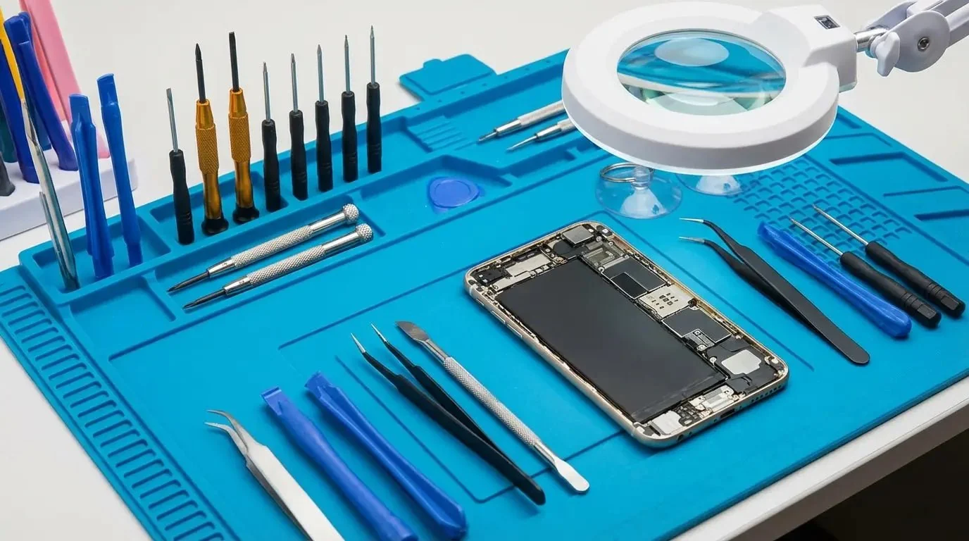
Diagnosing the fault is the first and most important step before any kind of reflow or repositioning of components is done. One of the main reasons that new technicians end up spending a lot on replacing the wrong chips or parts is their eagerness to act upon a wrong diagnosis.
A precision soldering station is frequently seen as merely a repair tool, but the fact is the technician’s toolbox has this tool also for doing diagnostic work. Indeed, some advanced workstations provide temperature ranges that are very mild, which are used mainly for the purpose of diagnostic reflow so the tech is able to do a “dry run” without harming any other parts.
Equipped with a multitester and a lab power supply having a current-limiting function, you will be able to track out short circuits, measure voltages on different power lines, and discover which component is consuming the lion share of current, all this without having touched a joint yet.
Thermal imaging cameras are another tool that has become a common part of professional electronic repair tools. A damaged component, which is shorted, will almost always heat up at a rate faster than that of the other parts on the board once the device is powered.
With the use of a thermal camera, locating the problem has been reduced to a visual identification task and is now almost an instant process compared to the old way of testing each point individually manually for many hours before a fault could be revealed.
Step Two: Seeing What You’re Working With
In this day and age, human eyes can’t even be trusted to spot logic boards’ tiny components. The only viable solution is to use a soldering microscope, which one could rightfully say is the biggest investment for someone who really wants to carry out the repairs at the board level.
With a good stereo microscope and adjustable objective lens magnification (typically from 3.5x to 45x), it is possible for technicians to examine BGA chip pads, locate very small trace damage like hairline cracks, and place components with an accuracy that’s just impossible using a loupe or simply by looking with the naked eye.
When choosing a microscope, technicians should prioritize the following:
- A stable boom-arm stand that doesn’t drift under vibration
- Adjustable LED ring lighting to reduce glare on reflective solder
- The ability to have a working distance sufficient enough to be able to work around the soldering tools comfortably
Ignoring this process and opting for poor replacements is certainly one of the quickest ways to ruin a board that could otherwise be saved.
Step Three: Component Removal and Board-Level Repair
Once a problem is localized and the defect is seen in the board, the repairing processes largely entail the chip removal and reballing of BGAs with BGA rework stations as well as the careful replacement of small components with hot air rework instruments and, finally, using the appropriate flux, which would facilitate ‘no-clean,’ low-residue soldering on multi-layer boards.
Corrosion damage, the physical deformation of pads, or boards carrying a history of botched repair attempts can require a motherboard grinding tool. This type of tool makes it possible to remove the corroded or damaged areas, the solder mask, or the excess epoxy from the surfaces of a board at the same time as not harming the copper layers underneath.
Misjudgment or poor skill in using a grinding device is enough to ruin a board completely; however, with proper technique and maybe the help of a magnifying glass, the device can be absolutely critical to boards that were going to be thrown away because of damage.
Building a Reliable Repair Bench
A dependable logic board repair setup generally includes the following:
- A precision soldering station with adjustable temperature control
- A high-magnification soldering microscope with stable mounting
- A hot air rework station
- A BGA reballing kit
- A digital multimeter and bench power supply
- A motherboard grinding tool for surface-level corrosion or damage repair
- ESD-safe mats and grounding straps to protect sensitive components
Investing in quality equipment upfront reduces the risk of secondary board damage — which, in board-level repair, is often more expensive than the original fault.
The Human Factor: Why Experience Still Matters
Tools by themselves do not make a skilled technician. The ability to read a schematic, know about power sequencing, and understand whether a board can be repaired beyond economical limits can all be attributed to experience with real-world situations.
Top-class repair shops use state-of-the-art equipment while their technicians work under the microscope for many hours, getting their brains filled with the knowledge of what goes wrong in board failures and what could cause them.
The level of trust customers have also depends on this stage: a repair service that properly diagnoses an issue before providing a quote, tells you the problem exactly, and employs high-quality tools is definitely more worthy of your trust and respect than one that gives you guesswork “flat rate” fixes.
Conclusion
Logic board repair is a perfect mix in a highly precise, patient, and very equipment-intensive way of a few key factors. From correctly identifying the exact issue to using the soldering microscope very carefully and, if that’s even required, using a motherboard grinding tool, each detail is important.
Repair people who have invested in the best equipment as well as the corresponding tools training have not only shown to deliver consistently good results, but also have managed to keep many boards alive and the kind of word that brings the same customers back.
Frequently Asked Questions
1. What’s the difference between board-level repair and standard phone repair?
Repair of devices by replacing external, easily accessible parts (such as screens or batteries) is considered standard. Repair involving the board-level, that is the logic board, requires that it is first checked and repaired, this is the much more technically demanding job that will require specialized tools and a good knowledge and understanding of electronics.
2. Do I really need a microscope for phone repair, or is a magnifying glass enough?
A magnifying glass won’t even come close to the level of detail that is required to view today’s printed circuit boards. The components are not only tiny, but they are also crammed so close together that a genuine soldering microscope is the only way to carry out the job precisely without risking harm to the nearby electronics.
3. Can a damaged logic board always be fixed?
It really depends on the circumstances. If the logic board has extensive corrosion spots, multiple components have popped up, or it’s badly water-damaged, then these cases can be beyond repair, either from a physical or economic perspective, regardless of the tools available.
4. How much does it cost to set up a basic micro-soldering repair station?
Cost varies a lot according to the standard of the equipment, but generally speaking, a basic setup that includes a soldering station, a microscope, and a hot air rework tool, all of which work well together, would require a modest initial investment.
5. Can I teach myself micro-soldering?
Of course, but in doing so, you will commit a lot of time and energy for a hobby. A number of professional technicians use practice boards as a starting point; they get micro-scopy instruments very early on and then gradually build up skills by being exposed and repeatedly working without hurrying themselves right into fixing customer equipment.
.